- 您现在的位置:买卖IC网 > Sheet目录476 > MDEV-433-HH-LR8-MS (Linx Technologies Inc)KIT DEV TX 433MHZ MS SER LONG-RG
�� �
�
�SETTING� THE� TRANSMITTER� ADDRESS�
�The� MS� Long-Range� Handheld�
�Transmitter� allows� the� selection� of� one�
�of� 16,777,216� (2� 24� )� unique� addresses.�
�THE� DECODER� BOARD�
�The� decoder� board� included� with� the� evaluation� kit� uses� an� LR� Series� receiver�
�to� receive� the� signal� from� the� Handheld� transmitter� and� then� feeds� it� into� an� MS�
�Series� decoder.� The� board� is� designed� to� allow� full� access� to� the� many� features�
�All� transmitters� are� supplied� set� to� the�
�same� address.� To� avoid� contention� with�
�other� units� or� to� create� unique�
�relationships,� the� address� can� be�
�changed.� This� is� accomplished� by� using�
�a� paper� clip� or� probe� to� press� the�
�CREATE� button� on� the� board� through�
�the� hole� in� the� back� of� the� case.� Press�
�the� button� and� a� LED� will� light� up� in� the�
�MODE_IND� window,� indicating� that� the�
�MODE_IND� Window�
�CREATE� B� u� tton�
�Figure� 2:� CREATE� Button� Access�
�of� the� decoder� and� to� speed� development� and� integration� of� the� LR� and� MS� into�
�a� product.� The� following� sections� describe� the� features� of� this� board� in� detail.�
�The� Prototyping� Area�
�The� prototyping� area� on� the� decoder� board� contains� a� large� section� of� plated�
�through-holes� so� that� external� circuitry� can� be� placed� on� the� board.� This� circuitry�
�can� be� interfaced� with� the� MS� Series� decoder� through� the� breakout� header� to� the�
�right� of� the� holes.� At� the� bottom� of� this� area� is� a� row� connected� to� the� 3V� power�
�supply� and� at� the� top� is� a� row� connected� to� ground.�
�All� of� the� data� lines� are� connected� to� a� wire-wrap� header� to� the� right,� allowing�
�address� is� being� created.� The� address� will� be� randomized� for� as� long� as� the�
�button� is� held� down.� Release� the� button� and� the� randomized� address� will� be�
�saved� and� the� LED� will� begin� flashing� to� indicate� that� the� Control� Permissions�
�may� now� be� set.� Press� the� buttons� that� the� transmitter� will� have� the� authority� to�
�access.� Press� the� CREATE� button� with� the� paper� clip� again� or� wait� 17� seconds�
�for� it� to� time� out.� The� address� and� Control� Permissions� are� now� set.� The� decoder�
�will� need� to� learn� the� address� before� it� will� accept� any� transmissions.� Please� see�
�the� Typical� Applications� section� of� this� data� guide� or� the� MS� Series� Decoder�
�Data� Guide� for� details.�
�OTX-***-HH-LR8-MS� BUTTON� ASSIGNMENTS�
�This� diagram� illustrates� the� relationship� between� the� button� locations� and�
�encoder� data� lines.�
�easy� access� from� the� prototyping� area.� The� Decoder� Data� and� TX� ID� lines� are�
�also� available� on� the� header� as� well� as� the� PDN� line� from� the� RF� module.� This�
�allows� complete� control� of� the� entire� system� from� the� prototyping� area,� giving� the�
�designer� a� great� deal� of� flexibility� in� using� the� board.�
�The� Power� Supply�
�The� power� supply� on� the� decoder� board� consists� of� a� standard� 9V� battery� and�
�power� jack� connected� to� a� 3.0V� voltage� regulator.� It� can� provide� approximately�
�500mA� of� current� to� the� prototyping� area.� If� the� added� circuitry� will� need� more�
�than� this,� the� designer� must� add� an� external� supply.� If� the� circuit� will� consistently�
�draw� more� than� 100mA� of� current,� it� might� be� better� to� use� the� power� jack� rather�
�than� the� battery,� as� the� battery� may� run� down� fairly� quickly,� reducing� testing� and�
�development� time.�
�The� jack� accepts� a� standard� 5.5mm� plug� with� the� tip� ground� and� the� outer� shell�
�7� to� 16VDC� positive� supply.� While� a� reverse� voltage� protection� diode� has� been�
�included� on� the� board� to� protect� the� circuitry� in� case� the� voltage� on� the� plug� is�
�reversed,� it� is� still� a� good� idea� to� double-check� the� polarity.�
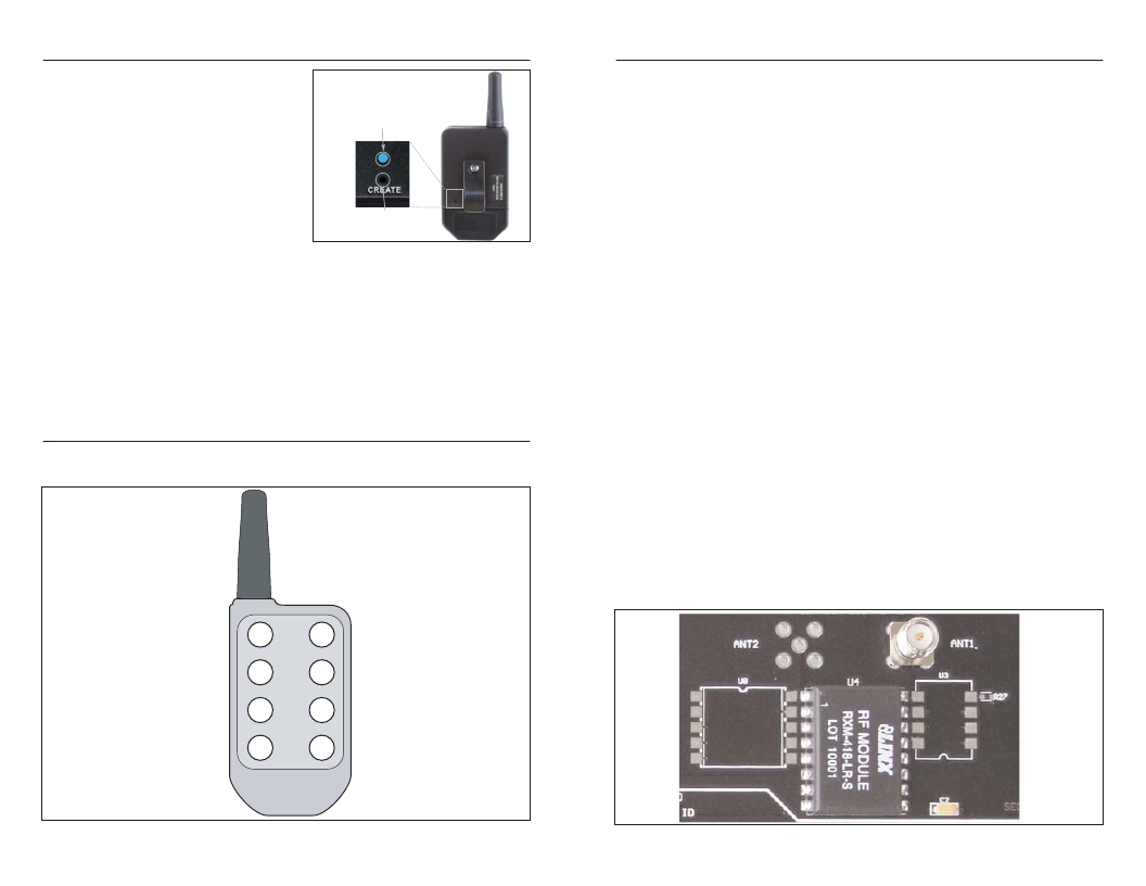
�The� RF� Area�
�The� figure� below� shows� the� RF� area� of� the� development� board.� The� board� uses�
�the� LR� Series� receiver� as� shown.� Attach� the� included� antenna� to� the� reverse�
�polarity� SMA� connector� before� operation.�
�D6�
�D4�
�D2�
�D0�
�Figure� 3:� OTX-***-HH-LR8-MS� Button� Assignments�
�Page� 4�
�D7�
�D5�
�D3�
�D1�
�Figure� 4:� The� Decoder� Board� RF� Area�
�Page� 5�
�发布紧急采购,3分钟左右您将得到回复。
相关PDF资料
MDEV-869-ES-USB
KIT MASTER DEV 869MHZ ES USB
MDEV-900-HP3-PPS-RS232
KIT MASTER 900MHZ HP-3 SIP RS232
MDEV-900-HP3-SPS-USB
KIT MASTER 900MHZ HP-3 USB SMD
MDEV-900-NT
TRM 900 NT MASTER DEV SYSTEM
MDEV-GPS-SG
KIT MASTER DEV GPS SG SERIES
MDEV-GPS-SR
KIT MASTER DEV GPS SR SERIES
MDEV-LICAL-HS-ES
KIT MASTER DEV HS ES RF MODULES
MDEV-USB-QS
KIT DEV MASTER USB QS SERIES
相关代理商/技术参数
MDEV-433-RM
功能描述:KIT MASTER EVAL 433MHZ RM SERIES RoHS:否 类别:RF/IF 和 RFID >> 过时/停产零件编号 系列:- 标准包装:1 系列:- 类型:用于 200/300 系列的欧盟开发套件 适用于相关产品:Zensys RF 模块 所含物品:开发板,模块,编程器,软件,线缆,电源 其它名称:703-1019Q3225667
MDEV-868-NT
功能描述:射频开发工具 NT Series Dev Kit w/ Transparent Module
RoHS:否 制造商:Linx Technologies 产品: 类型: 工具用于评估: 频率: 工作电源电压:
MDEV-869-ES-RS232
功能描述:射频开发工具 ES Master Dev Sys 869MHz, RS232 Module
RoHS:否 制造商:Taiyo Yuden 产品:Wireless Modules 类型:Wireless Audio 工具用于评估:WYSAAVDX7 频率: 工作电源电压:3.4 V to 5.5 V
MDEV-869-ES-USB
功能描述:射频开发工具 ES Master Dev Sys 869MHz, USB Module
RoHS:否 制造商:Taiyo Yuden 产品:Wireless Modules 类型:Wireless Audio 工具用于评估:WYSAAVDX7 频率: 工作电源电压:3.4 V to 5.5 V
MDEV-900-HP3-PPS-RS232
功能描述:KIT MASTER 900MHZ HP-3 SIP RS232 RoHS:否 类别:RF/IF 和 RFID >> RF 评估和开发套件,板 系列:HP3 标准包装:1 系列:- 类型:GPS 接收器 频率:1575MHz 适用于相关产品:- 已供物品:模块 其它名称:SER3796
MDEV-900HP3PPS-RS232
功能描述:射频开发工具 HP-3 Master Dev Sys Pinned, RS232 Module
RoHS:否 制造商:Taiyo Yuden 产品:Wireless Modules 类型:Wireless Audio 工具用于评估:WYSAAVDX7 频率: 工作电源电压:3.4 V to 5.5 V
MDEV-900-HP3-PPS-USB
功能描述:射频开发工具 HP-3 Master Dev Sys Pinned, USB Module
RoHS:否 制造商:Taiyo Yuden 产品:Wireless Modules 类型:Wireless Audio 工具用于评估:WYSAAVDX7 频率: 工作电源电压:3.4 V to 5.5 V
MDEV-900-HP3-SPS-RS232
功能描述:KIT MASTER 900MHZ HP-3 RS232 SMD RoHS:是 类别:RF/IF 和 RFID >> RF 评估和开发套件,板 系列:- 标准包装:1 系列:- 类型:GPS 接收器 频率:1575MHz 适用于相关产品:- 已供物品:模块 其它名称:SER3796